

Uninterruptible power supplies operating in parallel refers to when the outputs of two or more UPS are connected to supply the load via a common AC busbar.
There are two main configurations:
- Parallel-Capacity (N) where the total load demand is met by a number of UPS without the provision of any redundancy
- Parallel-Redundant (N+X) where the total load demand is met by all the UPS sharing the load between themselves equally. If one of the UPS fails, the remainder are able to continue supporting the load.
Parallel-Capacity (N) UPS Systems
‘N’ configuration solutions do not increase system resilience because they lack redundancy, they simply enable increased overall capacity by connecting multiple UPS to work together. The total capacity is calculated by the number of UPS modules used (also known as a Total Power System).
Because of the lack of redundancy, carrying out maintenance on a parallel-capacity installation means bypassing the entire UPS system so that one or more modules can be powered down for service. During UPS maintenance, the load is powered directly by the mains supply, so it is unprotected to any interruptions.
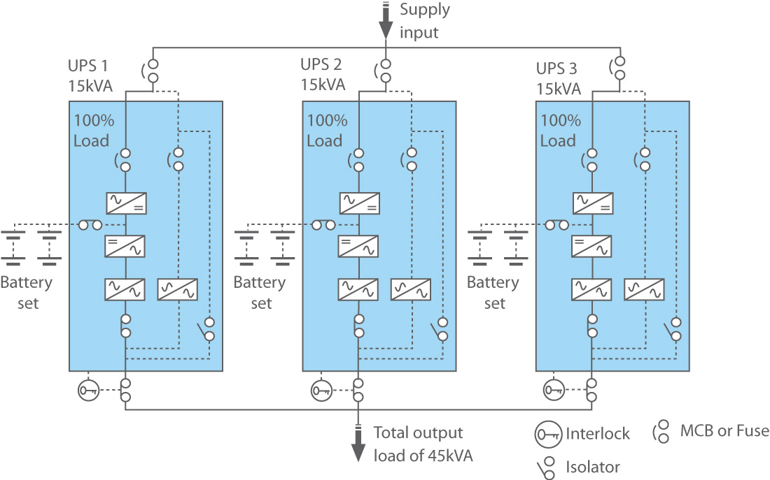
The below image shows a parallel-capacity 45 kVA power system comprised of three 15 kVA UPS operating at 100% load.
Parallel-Redundant (N+X) UPS Systems
‘N+X’ configuration solutions are commonly used to protect mission-critical applications in data centres, industrial sites and larger business operations. The main principle behind a parallel-redundant UPS system is that it can continue to support the critical load should one or more UPS modules fail. Compared to N capacity installations, this means it can achieve higher availability and MTBF (mean time between failure).
In addition, this also enables UPS maintenance to take place without interrupting the load. Modules can be powered down for servicing while the remaining UPS continue supporting the load.
The below image shows a parallel-redundant 30 kVA N+1 power system comprised of three 15 kVA UPS equally sharing the load (10 kVA per UPS).
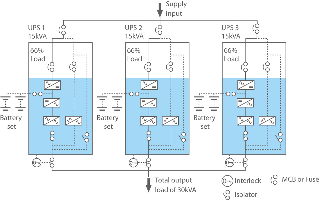
During normal operation, each UPS shares the load equally. Similarly, when the UPS system needs to run on batteries, each UPS will still share the load as each module has its own battery set, rather than a shared common battery.
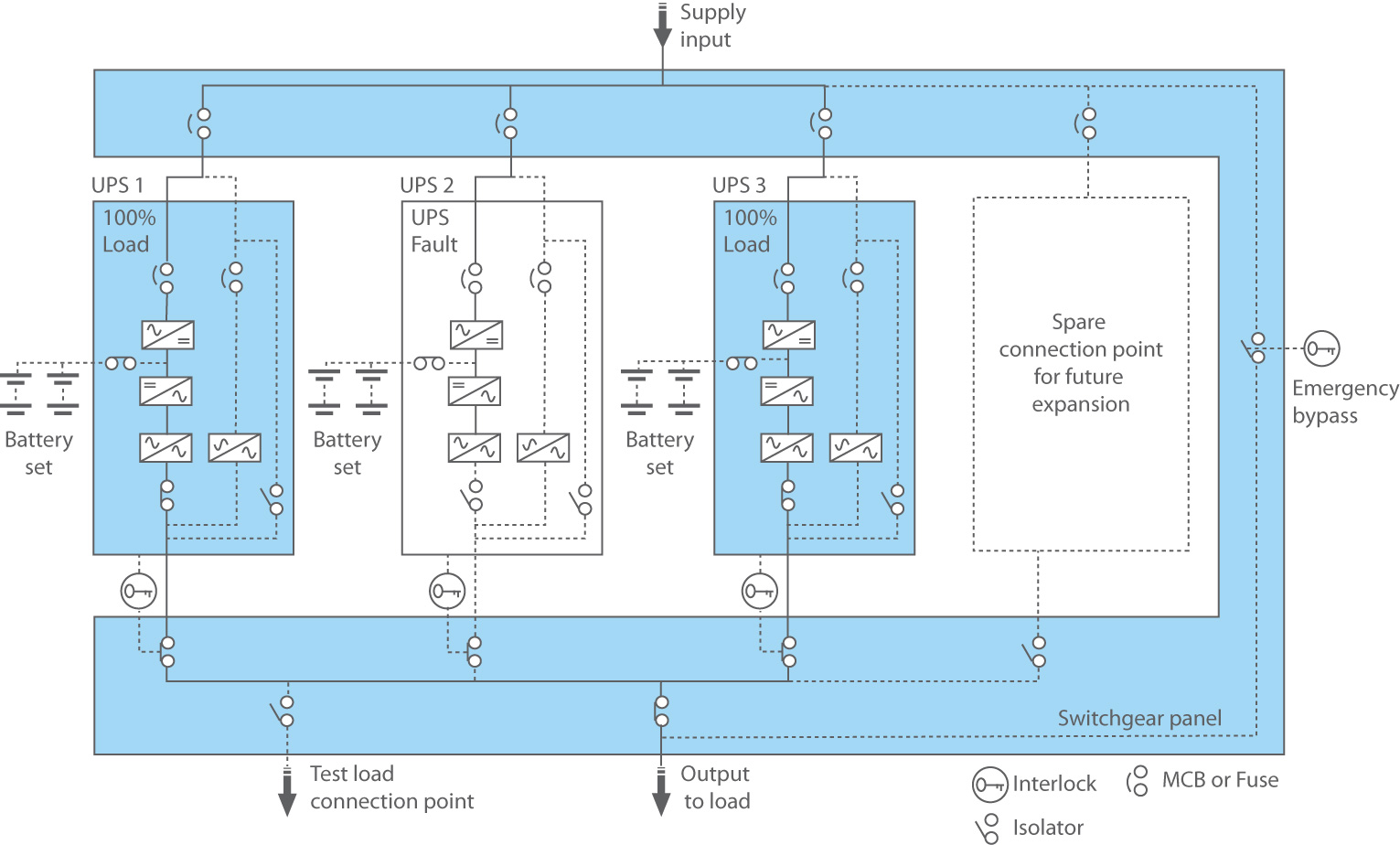
If any of the UPS modules in a parallel-redundant configuration fails or experiences an internal fault, it automatically disconnects from the output AC busbar, while the remaining active UPS continue sharing the load.
The below image shows a parallel-redundant system containing three 100 kVA UPS supplying a total load of 200 kVA. When ‘UPS 2’ fails, the remaining active units take over the load.
In the example above, if either ‘UPS 1’ or ‘UPS 2’ were to fail, the one remaining operational module will go into an overload condition and transfer to bypass via its static switch. This will simultaneously force the two faulty UPS into bypass, ensuring the load continues to receive power.
Other Redundant UPS Configurations
In addition to parallel-capacity and parallel-redundant, there are other configurations to consider:
- Isolated-Redundant: this is sometimes known as N+1 but it differs considerably to a parallel-redundant N+1 installation. In this configuration, there’s a main UPS module that feeds the load, while the secondary UPS feeds its static bypass. When a fault causes the primary UPS to transfer to bypass, the secondary module accepts the full load.
- Distributed-Redundant: also known as Tri-Redundant and typically used in large multi-megawatt data centres. Made up of three or more UPS with independent input and output feeders, with the output buses connected to the load by several PDUs (and in certain cases Static Transfer Switches). This configuration does minimise single points of failure and offers the opportunity for concurrent maintenance, but it also leads to significant load management challenges.